Finalization of the building model
Before you start working with structures, you need to finalize the model created earlier.
Let's make the floor monolithic:
- Right-click any floor on the 01-Floor level and select the Select > Similar on level on the shortcut menu.
- Then select the Isolate command in the context menu.
- Select the Floor
 tool and the Automatically by similar
  construction mode.
 - In order new slab does not intersect with the current floor, please specify in the Parameters panel:
- Leave the other parameters at their default values.
- Move the mouse cursor to the external border of one of the existing floors. A ghost image of the border of new floor will appear. Fix the position by left clicking the mouse.
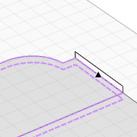
- In the same way, point to the other borders of the floor. When the overlap contour matches, press Enter.
- Select the Select tool
 .
. - Select the new floor, in the parameters, set Vertical offset
 to 0 mm. Then hide new floor.
 - Select the old floors on the Base level and delete them by pressing Delete.
- Select the Show all... command in the context menu.
- To work with floor at another level, place the working plane on it.
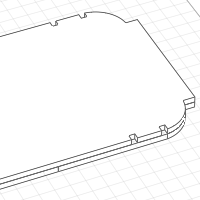
- Rebuild the floors at all levels, the layered material is Interfloor.
|
|
Layered material. |
First floor |
|
|
Vertical offset. |
400 |

As the townhouse project involves reinforcing carrying walls, columns, beams, floors, let's prepare the filter. To create a new filter:
- On the Primary panel, click Manage styles
 – Filters
  .
. - In the Filters editor, create a new filter by clicking the New filter
 button.
 - Set the name of the new filter to Carrying Structures.
- On the right side of the window, specify a new property by clicking the Add group button.
- In the Add group window, specify the following filter rules:
- Object type: Wall;
- Property: Wall thickness, mm;
- Operator: is greater than or equal to;
- Value: 400.
- Click the Add button.
- Click OK.
- In the same way, specify the following filter rules for the Beam, Column, Floor object types:
- Property: Name;
- Operator: any value.
- Click OK.
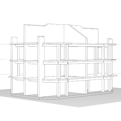
Right-click the work plane on 3D view and select Isolate > Carrying Structures on the shortcut menu.
As the result, the model should look like figure below.
Creating Schedules and Assigning Tags
We will create schedules to assist in assigning tags to the carrying structures.
To determine column tags, we will use the quantities of Level and Net Volume:
- In the Project Explorer, in the Schedules group, click Create new schedule.
- Name the schedule Columns.
- Open the schedule.
- On the Commands panel, click the Insert schedule column to the right
 command.
 - In the left part of the window, select Column object type from the drop-down list.
- While holding down Ctrl, select Mark, Level, and Net Volume.
- Click OK.
- On the Parameters panel, in the
 View drop-down list, select the Aggregate identical records check and in the
  Sort by list, select the Level.
 - In the resulting schedule, assign column tags:
C-1
01-Floor
0,48
C-1
02-Floor
0,48
C-2
03-Floor
0,48
To determine wall tags, we will use the quantities of Level and Nominal length:
- Create a schedule as described above. Name the schedule Walls.
- When inserting a column, select Wall object type.
- While holding down Ctrl, select Mark, Level, and Nominal length.
- In the Parameters panel, set the Carrying Structures filter.
- On the Parameters panel, in the View drop-down list, select the Aggregate identical records check and in the
 Group by list, select the Level, in the Sort by list, select the Nominal length.
 - In the resulting schedule, assign wall tags:
01-Floor
W-1
6 000
W-2
7 000
W-3
10 000
02-Floor
W-3
1 282
W-1
6 200
W-3
10 000
03-Floor
W-5
1 200
W-1
6 200
W-3
10 000
Attic floor
W-6
1 200
W-7
6 000
W-8
10 000
Name the schedule Beams.
|
01-Floor |
|
|
B-1 |
1 414 |
|
B-2 |
3 141 |
|
B-3 |
4 000 |
|
B-4 |
5 000 |
|
B-5 |
6 000 |
|
02-Floor |
|
|
B-1 |
1 414 |
|
B-6 |
4 000 |
|
B-7 |
4 242 |
|
B-4 |
5 000 |
|
B-5 |
6 000 |
|
B-8 |
9 200 |
|
03-Floor |
|
|
B-9 |
4 000 |
|
B-10 |
5 000 |
|
B-11 |
9 000 |
Material selection
First, let's assign material to the columns and beams:
- Go to 3D View.
- Right-click on any column and select Select > Similar in project in the context menu.
- On the Parameters panel, select Concrete.
- Select the material for the beams in the same way.
For further work create layered materials for floors and walls.
In order to change layered material:
- Click the Layered materials on the Manage styles
 menu on the Primary panel.
 - Switch the Object type to Floor in the Layered materials editor.
- Select the First level floor.
- Set the Concrete material of the base in the right part of the window.
- On the right side of the window, select Interfloor.
- Set the Concrete material of the base in the right part of the window.
- Switch the Object type to Wall in upper part of the window.
- Select the Solidwall layered material. On the right side of the window, change the base material to Concrete and add Nonmetal layers on top and bottom of the concrete. The layers thickness is 10 mm.
- Click OK.
Set the floor parameters:
- Select the floor on the 01-Floor level. Change it's parameters. They are:
-
On the 02-Floor, specify the following parameters:

Mark.
F-2
-
On the 03-Floor, specify the following parameters:
Mark.
F-3
-
On the Attic floor, specify the following parameters:
Mark.
F-4
|
|
Mark. |
F-1 |
The model is prepared for work with reinforcement.