Documentation
After finalization of reinforcement design getting structural drafting.
You may have noticed that, in the Project Explorer, there is a drawing entitled as 01-Floor Plan. Copy it to get the Column and Wall Plan.
- In the Project Explorer select 01-Floor Plan and press CTRL+C
- Press Ctrl+V.
- Select a thumbnail and press F2 to rename.
- Set the drawing name - Column and Wall Plan.
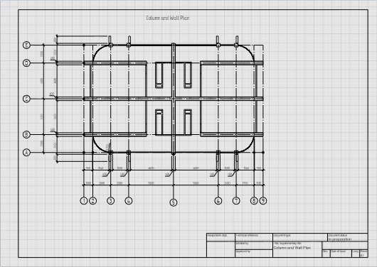
We'll proceed to executing the column and wall plan. First of all, a view should be edited. It is necessary to edit the view so that only walls and columns do appear in the drawing.
- Click the plan. You have selected View.
- It is necessary to change the display style of the view. In the Display style parameter, select Other.
- Create the Only columns and walls style in the appeared window.
- In the right part of window, remove the check mark in the Visibility column for all objects except doors, columns, windows and walls. And you must turn off the visibility of panel, swing and swinging panel for door.
- Click OK.
Grid lines and dimensions have already applied in the drawing. Remove the remaining of the section designation.
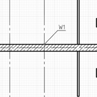
Now let's assign the tags to the walls and columns:
- On the Tools panel, click Designation
 – Tag
– Tag  .
. - On the Parameters panel, change the tag leader line to Solid.
- Move the pointer towards bearing wall and fix the mark position.
- Similarly, assign the tags to the other bearing structures.
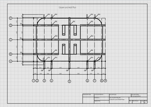
Making the column and wall plan is completed. Go to making drawings of reinforced concrete structures.
In the beginning, we need to create a new drawing in the project:
- Open the Project Explorer. Click Create new drawing.
- Set the drawing name - Column and Wall Reinforcement.
- Open the drawing by clicking its thumbnail.
- Specify page parameters:

Page format.
A3

Page orientation.
Album

Layout style.
Compact form
- The project name will automatically display in the title block. To add a drawing name, enter the text {Name} in the cell.
Let's edit the Display style that is already in the project:
- On the Primary panel, click Manage styles
 – Design – Display styles
  .
. - In Display styles editor choose Simplified reinforcement style.
- Check the Visibility of Rebars.
- Set the Thickness of the projection line to 0.5 mm and the Color of the projection line to Black.
- Click OK.
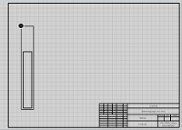
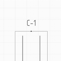
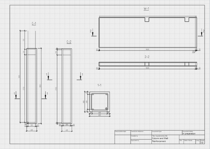
We'll proceed to creating the C1 column drawing.
- Click the Object
 tool.
tool. - Set object parameters:
- Specify the insertion point of object in the sheet.

|
Object mark. |
C-1 |

|
Object view. |
Front |

|
View name. |
none |

|
Object scale. |
1:20 |

|
Visual style. |
Wireframe |

|
Display style. |
Simplified reinforcement |
Now let's assign the tag to the column:
- On the Tools panel, click Designation – Tag .
- Specify the following parameters:
- Move the mouse cursor to the column.
- Fix the tag position and press Esc.
- Move the caption up 10 mm.

|
Tag style. |
Default |

|
Tag leader line. |
Hidden |

|
Tag orientation. |
Horizontal |

|
Text alignment. |
Left |

|
Text style |
Designation |
Now let's dimensioning.
- Select the Dimension
 tool. The dimension type is Linear Dimension
  .
. - In the dimension parameters, set Dimension scale to 1:20 and select Text style – Dimension. Leave the other settings at their default values.
- Estimate the column width by two points. Then move the pointer down and fix the dimension position by left-clicking the mouse.
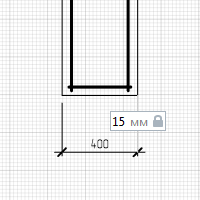
In the same way assign the other dimensions.
Create a drawing for C-2 column as described above.
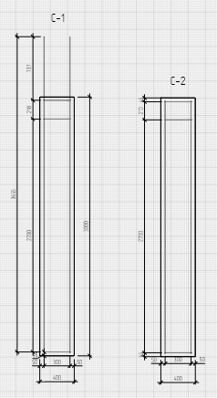
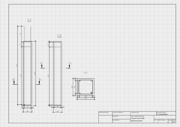
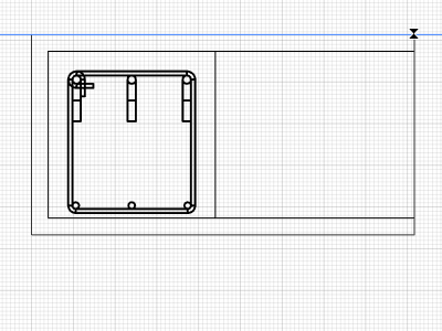
The section of the columns C-1 and C-2 is the same. Let's show it in the drawing.
- Click the Object tool.
- Set object parameters:
- Specify the insertion point of object in the sheet.
- Add dimensions to the section.
- In order to create a section name, click the Text
 tool.
tool. - Define the text insertion area by two points.
- In the Text editor, select the font and set its height to 5 mm.
- Enter text 1-1. And click OK.
- Then press Esc to reset the tool.
|
|
Object mark. |
C-1 |
|
|
Object view. |
Top |
|
|
View name. |
none |
|
|
Object scale. |
1:10 |
|
|
Visual style. |
Wireframe |
|
|
Display style. |
Detailed reinforcement |
Let's create section designation of C-1 and C-4 columns.
- Click the Designation tool. Section
 designation type.
 - Select the Section in one plane
 section type .
 - Section Parameters:
- Specify points of section designation in the middle of C-1 column.
- Then, change the section name to 1 again and add section designation to C-2 column.

|
Section name. |
1 |

|
Section line extension. |
5 |
|
|
Text style |
Designation |
Create the drawing for W-3 wall by using the knowledge you acquired earlier.
Create new drawing Slab F1. Formwork as described above.
To create a formwork drawing, do following:
- Click the Object tool.
- Set object parameters:
- Specify the insertion point of object in the sheet.
- Add dimensions on the drawing.
|
|
Object mark. |
F1 |
|
|
Object view. |
Top |
|
|
View name. |
none |
|
|
Object scale. |
1:100 |
|
|
Visual style. |
Monochrome |
|
|
Display style. |
For objects |
Create a new A2 size drawing as follows:
- Create new drawing. The name is Floor F-1. Reinforcement.
- Open the new drawing.
- Specify page parameters:
Page format.
A2
Page orientation.
Album
Layout style.
Compact form
- The project name will automatically display in the title block. To add a drawing name, enter the text {Name} in the cell.
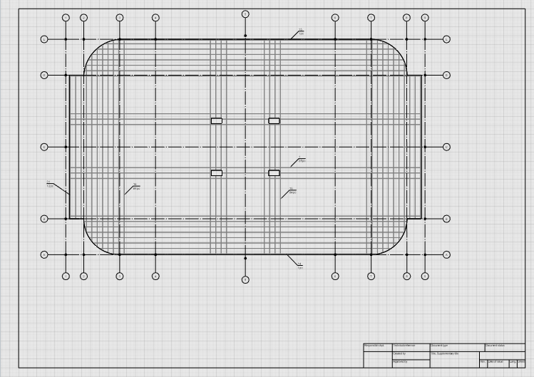
To create a floor reinforcement plan, create a filter that leaves only floor F-1 in the view:
- On the Primary panel, click Manage styles –
 Filters.
 - In the Filters editor, create a new style by clicking New filter
 .
. - Set a new name of the filter - Floor F-1.
- On the right side of the window, set a new property by clicking the Add group button.
- In the Add group window, specify the following filtration rules:
- Object type: Floor;
- Property: Mark;
- Operator: equals;
- Value: F-1.
- Click the Add button.
- Click OK.
- Click OK in the editor.
Then insert foundation slab with place a reinforcing meshes and construct documents as following:
- Click the View
 tool.
tool. - Specify view parameters:
- Select the insertion point in the sheet.
- On the Tools panel, click Designation – Grid line
 – Automatically by view
  .
. - Move the mouse cursor to the view.
- On the Tools panel, click Designation – Tag .
- Set the tag parameters:
Tag style.
Mark and style of the reinforcement
Tag leader line.
Close arrow
Tag orientation.
Horizontal.
Text alignment.
Align Text Left
Text Style.
Designation
- Move the mouse cursor to symbolic mesh image. A mark of rebar will appear.
- Fix the tag position.
- Finish the scheme of place a reinforcing meshes documentation as following:
|
|
Object mark. |
01-Floor |
|
|
View scale. |
1:50 |
|
|
Visual style. |
Wireframe |
|
|
Display style. |
Simplified reinforcement |

|
Filter. |
Floor F-1 |

|
View depth plane offset. |
-100 |
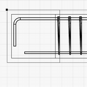
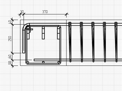
Let's consider the creation of the beam junction drawing for B-9 and B-11 beams as example:
- In a new drawing, click the Object tool.
- Set object parameters:
- Specify the insertion point of object in the sheet.
- On the Parameters panel, specify the parameters to insert another beam:
- Place the object in the drawing with snap to the upper left corner of the B-11 frame as follows:
- Press Esc and reduce the size of the B-11 frame.
- Add dimensions on the drawing.
|
|
Object mark. |
B-11 |
|
|
Object view. |
Front |
|
|
View name. |
none |
|
|
Object scale. |
1:10 |
|
|
Visual style. |
Wireframe |
|
|
Display style. |
Detailed reinforcement |
|
|
Object mark. |
B-9 |
|
|
Object view. |
Right |
By using the knowledge you acquired earlier, create detailed view of the beams connection so that the B-9 beam would be displayed in front and B-11 beam would be displayed on the right.