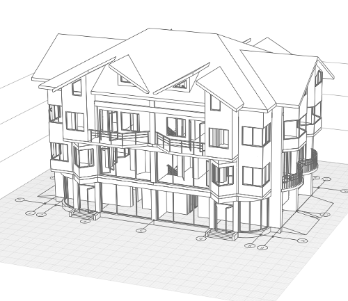
Project Model Creation
Let's start to create a model of townhouse. A townhouse for 4 families consists of 4 symmetrical sections. Each section occupies an area of 10х6 m2.
We'll begin with the working plane preparation.
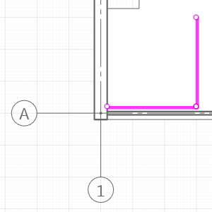
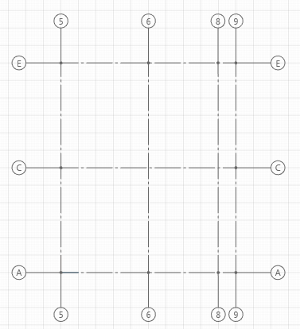
In order to estimate the placement of the first section, mark up the work plane with the Grid line designation:
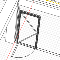
- Holding the right mouse button, rotate the working plane so that the grid lines are positioned as shown in the picture.
- On the Tools panel, click the Designation
 tool. In the Designation type panel that appears, select Grid Line
  and Line by specifying two points
  construction mode.
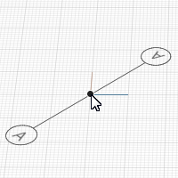
 - On the working plane, select the grid line start point:
- Move the mouse cursor to the conventional datum point (0,0) on the working plane.
- Press the Shift button. Left-click to fix the position when the point appears in the grid node.
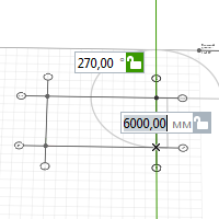
- Then specify the second point by the dynamic input fields:
- After specifying the first point, set the grid line length to 10 000 mm.
- Switch over the entry field by pressing the TAB key.
- Set the grid line rotation angle value in relation to X axis to 0°.
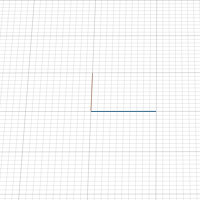
- Fix the grid line position by left-clicking the mouse.
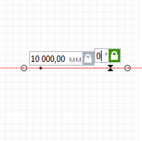
- The first grid line has been constructed.
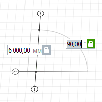
- Pay attention to the panels that are below the Tools panel. Before building the next grid line, change the Grid line name
 parameter to 1.
 - Construct the second grid line from point 0,0 perpendicular to the first one. The grid line length is 6000 mm, the angle is 90°.
- Construct grid line B in parallel to grid line A:
- Define the first grid line point at the end of grid line 1.
- Keep the mouse cursor at the parallel grid line end point to call tracking snaps..
- Move the mouse cursor to the expected point of intersection of auxiliary rays constructed from these points. A new snap point will appear.
- Click the left mouse button.
- Construct grid line 3 parallel to grid line 1 using object snaps at the ends of objects.
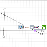
- Midway between grid lines 1 and 3, we'll construct grid line 2 using a snap to the middle of grid lines A and B.
- Move the mouse cursor to the middle of grid line A - an object snap to the middle of the straight line will appear. Fix the grid line point by left-clicking the mouse.
- Define the second point in the middle of grid line B in the same way.
- Move the mouse cursor to the middle of grid line A - an object snap to the middle of the straight line will appear. Fix the grid line point by left-clicking the mouse.
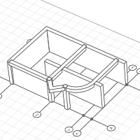
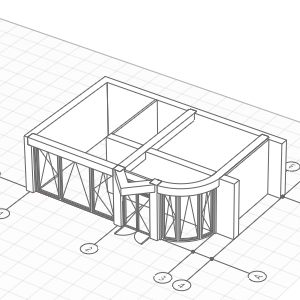
There should be a garage and hall in the townhouse 01- Floor. In addition, there should be a stair leading to the 02-Floor.
We cannot accommodate quite a large hall in the available area but it should be light enough and the garage should be suitable to fit a car.
Before building the floor, create the material that will be assigned to the objects. Materials define the object hatching and the color of their surfaces.
In order to create a new material:
- On the Primary panel, click
 Manage styles –
  Materials.
 - In the Materials editor, create a new material by clicking the New Material button
 .
. - Set the new material name - Nonmetal.
- On the right side of the window, select a color for the building elevation:
- On the color list, select Other.
- Select an appropriate color by using palette.
- Leave the other settings unchanged. You can assign them later.
- Click OK.
Create the layered materials that will be assigned to walls and floors:
- On the Primary panel, click Manage styles –
 Layered materials.
 - In the Layered materials editor, the Wall object type is selected by default. Create a new material by clicking the New material button .
- Set the new layered material name - Solidwall.
- In the right part of the window set the base material Nonmetal, layer thickness 400 mm.
- Then create a layered material External wall, base material is Nonmetal, layer thickness is 200 mm.
- Then create a layered material Partition, base material is Nonmetal, layer thickness is 100 mm.
- Then in the upper left part of the window switch Object type to Floor, create layered material Interfloor, base material - Nonmetal, layer thickness - 200 mm.
- Create another layered material First level floor, material - Nonmetal, layer thickness - 400 mm.
- Click OK.
The layer material and thickness can be changed during the design of the project.
To see how the color model looks, on the Primary panel click Visual style – Color. You can do this any time, but let's go on with the Monochrome visual style.
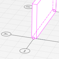
Let's build the bearing walls between the sections:
- Select the Wall
 tool. Select the Automatically by similar
 construction mode.
 - On the Parameters panel specify the following parameters:

Wall height
3000

Layered material Solidwall - Leave the rest parameters default.
- Move the mouse cursor to grid line 1. Phantom view of the wall will appear. Left-click to fix the wall position.
- Build the wall by similar of grid line B in the same way.
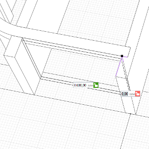
Now let's build another wall that will separate the garage from the hall:
- Click the Line by specifying two points wall construction mode.
- To specify the first point of the wall, we will use the tracking snap.
- Keep the pointer onto the intersection of grid lines A:3. Type 2000 mm in the dynamic input field.
- Move the pointer towards grid line B and left-click to fix the point position.
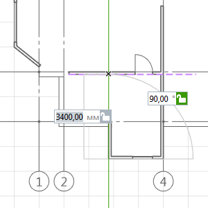
- Then use the dynamic input fields to construct a 7000 mm long wall parallel to grid line A.
Put columns at the entrance room. Firstly, create a new style of column:
- Click the Column Styles
 command in the Manage styles menu on the Primary panel.
 - In the appeared window, click the New column style button. Set the new style name to Square 400x400.
- At the right part of the window, on the list, click the Rectangle shape profile. Set the shape width and depth to 400 mm.
- Click OK.
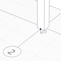
Now let's arrange the columns:
- Click the Column
 tool.
tool. - On the Parameters panel specify the following parameters:
- Define the column position at the intersection of grid lines A:2.
- Put one more column using the snap to the grid node. The distance between the columns center points is 2000 mm.

|
Column profile position relative to axis. |
Center |

|
Column style. |
Square 400x400 |
|
|
Column Height. |
3000 |
|
|
Material. |
Nonmetal |
Let's slightly extend the wall located on grid line 1:
- Select the Select tool
 .
. - Left-click on the wall located on grid line 1 to select it.
- On the Actions panel, click Trim or extend
 .
. - Specify the edge of the column.
- The wall extended.
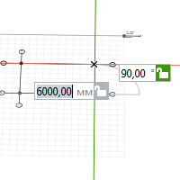
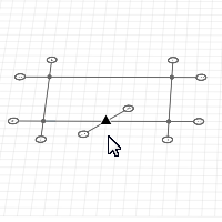
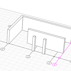
For further work, one more grid line between grid lines 2 and 3 will be required:
- Click the Select tool to select grid line 3.
- Holding Ctrl, click the handle.
- Move the pointer and make sure that the new grid line phantom view is following the pointer.
- Move the pointer to the grid node located by 1000 mm closer to grid line 2 and press Shift.
- Left-click to fix the grid line position.
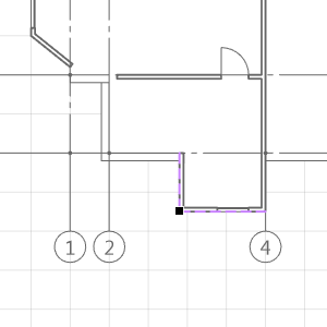
- Select the previous grid line and change the designation to 4.
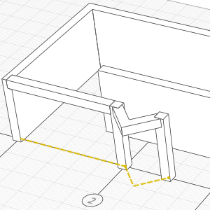
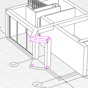
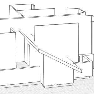
Next, let's put beams at the height of 2.6 m.
- Select the Beam
 tool. Click the Line by specifying two points construction mode.
 - Select Other on the Beam style list.
- Click the New beam style button in the appeared window. Set the new style name - Square 400.
- At the right part of the window, on the list, click the Rectangle shape profile. Set shape width and height - 400 mm. Click OK.
- Edit the beam parameters:
- Use snaps to construct straight beams in the following way:
- Not interrupting the construction, click the new construction mode – Arc by specifying start, center, end points
 . If construction is continuing, then start point of the arc has already been defined.
 - Specify the center point of arc on the center snap line of the wall so that the wall and auxiliary ray will be perpendicular.
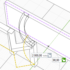
- Specify the end point of the beam at the intersection of grid line 3 and the wall central snap line.
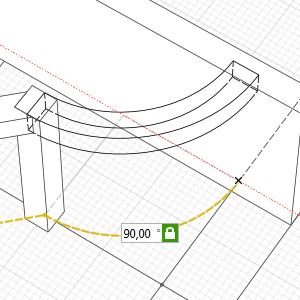
- Not interrupting the construction, click the new construction mode – Line by specifying two points and specify the second point at the intersection of B:3 grid lines.
- Uninterrupted beam construction is completed, press the Esc to separately build another beam.
- Build one more beam automatically by similar of grid line 2.
|
|
Beam profile position relative to axis. |
Top-Center |

|
Beam Style. |
Square 400 |
|
|
Vertical offset. |
2600 |
|
|
Material. |
Nonmetal |
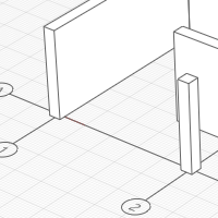
Doors and windows in Renga can be built within walls only. Let's build external walls:
- Select the Wall tool. Click the Line by specifying two points construction mode.
- On the Parameters panel, set the Layered material External wall.
- In order to define point 1 of the wall, use the snap to the intersection of the rib of the wall located on grid line 1 and grid line A.
- In order to specify the second point of the wall, use the snap to the intersection of the column rib located at the intersection of grid lines A:2 and grid line A.
- Press Esc to stop construction.
- Build a dividing wall between the columns in a similar way.
- Then construct an arc wall in the same way as the arc beam was built.
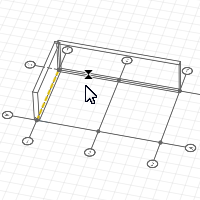
For gates, let's build a wall on the external side of the beam located on grid line 3:
- In order to have a snap to the beam, switch the measure mode to Cubic.
- Right-click the work area to open the shortcut menu.
- Select Measure mode – Cubic.
- Select the Line by specifying two points wall construction mode.
- Change the wall parameter as follows:
- Using snaps, specify a intersection point of the beam and the wall on the work plane. Construct a wall handles from left to right.
- Press Esc to stop construction. Then switch the measure mode back to Polar.
- Another partition for the garage, create a partition inside the building by choosing a layered material Partition.

|
Wall position relative to baseline. |
Right |
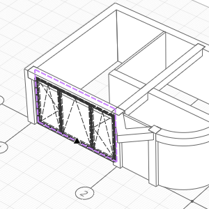
Let's insert the windows:
- Select the Window
 tool .
 - Set window parameters:

Window height
2600

Window width
4500

Vertical offset
0

Window style
Triple
- Put the window into the wall using a snap to the middle of the wall.
- In the Parameters panel, change the window width to 2600 mm. Put the window in the arc wall.
Let's place doors and gates:
- Click the Door
 tool.
tool. - In the door parameters, there is no Double-Panel Swing (Glass) style on the Door styles
 list. Let's create it:
 - Select Other.
- In the appeared door style editor, click the New Door Style button . Set the new style name to Double-Panel Swing (Glass).
- Click Add panel in the upper right corner of the window.
- Click the panel located on the left, it will highlight in pink.
- Specify the door settings on the lists at the top of the window – Swing | Left | Glass.
- For the right panel, specify the Swing | Right | Glass parameters in the same way.
- On the Parameters tab, select Glass for Transom construction.
- Then, type 500 for Transom height down below.
- Click OK.
- Set door parameters:
- Insert a door between columns using a snap to the middle of the wall.
- Before inserting a gate in the external wall located on grid line 3, change door parameters:
- To make an exit leading from the garage to house, put the door of 2100 mm height and 900 mm width at the distance of 100 mm from the wall, separating the garage and the internal area of the house, use the tracking snaps.
When building, calculate the distance of the door center location from the intersection point of the walls based on the door width.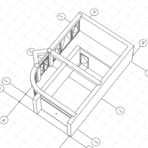
|
|
Door height. |
2600 |
|
|
Door width. |
1600 |
|
|
Door Style. |
Double-Panel Swing (Glass) |
|
|
Door height. |
2000 |
|
|
Door width. |
3600 |
|
|
Door Style. |
Single Vertical Sliding |
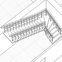
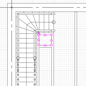
Now let's construct a stair to the 02-Floor:
- Select the Stair
 tool. Click the Line by specifying two points construction mode.
 - Specify the stair parameters:
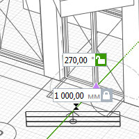
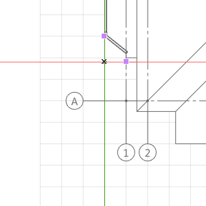
- On the work plane, specify the run of stairs first point at the distance of 1000 mm from the intersection of the dividing wall and the bearing wall:
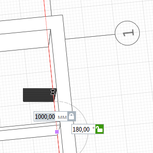
- Then specify the second point at the intersection of the walls.
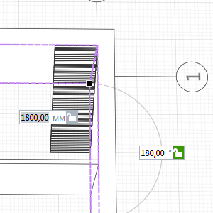
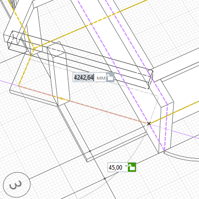
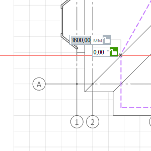
- Continue building the stair, set the length of the stair to 3800 mm and the rotate angle in relation to the Ox axis to 270° in the dynamic input fields. Fix the flight of stair's position by left-clicking the mouse.
- Then press the Enter key to finish the stair construction.
- Create railings. Click the Railing
 tool. Select the Place on stairs
  construction mode .
 - On the Parameters panel, set the Railing offset
 to 100 mm.
 - Move the pointer to the stair baseline. Move the pointer to the edge snap line of the stairs.
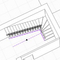
- Then build the railings on the other side.
|
|
Stair position relative to baseline. |
Left |
|
|
Stair width. |
1000 |

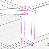
Near the stair, create a shaft for tech. communications and built-in wardrobe for overcoats by the methods of walls and doors construction you've already learnt.
When creating a wardrobe door, use the Double Sliding and Transom (Glass) door style.
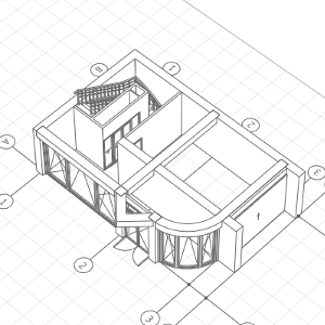
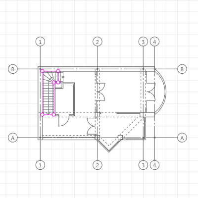
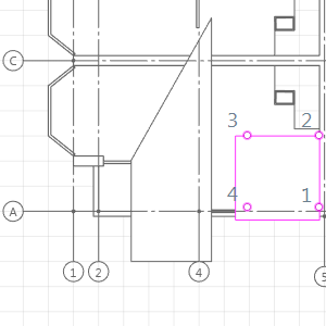
Finish construction of the 01-Floor. Create a floor taking into account the fact that the floor will be built for one of the symmetrical sections:
- Open the Project Explorer by clicking Open Project Explorer
 near the 3D View tab.
 - Click the Base level thumbnail. A 2D view of the floor has opened up in the new tab. Continue working in it.
- On the right, in the Parameters, set Section plane offset
 to 3000 mm.
 - Click the Floor
 tool. Select the Line by specifying two points construction mode.
 - In the parameters, set the layered material First level floor.
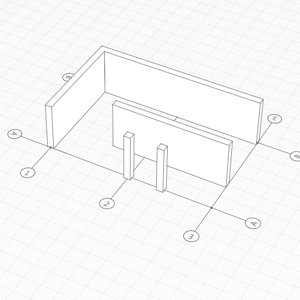
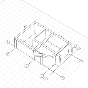
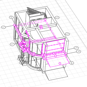
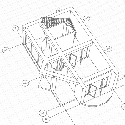
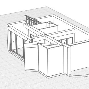
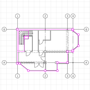
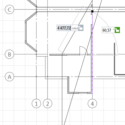
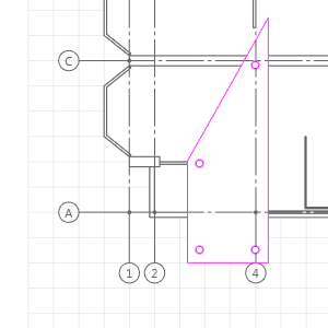
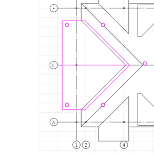
- Build the floor following the floor contour. Remember walls which located on the B and 1 axises, are adjacent to other sections of the townhouse. See the picture below during construction.
- To build an arc section of the floor, change the construction mode to Arc by specifying three points
 .
. - To finish the floor construction, press Enter.
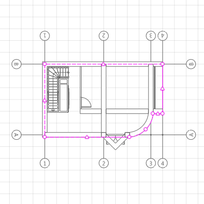
Create an opening in the floor for the technical services shaft.
- Select the Opening tool
 . Select the Line by specifying two points construction mode.
 - In the parameters, set the Opening depth
 to 400 mm.
 - Build an opening following the borders of the technical services shaft.
- Press Enter to finish the construction.
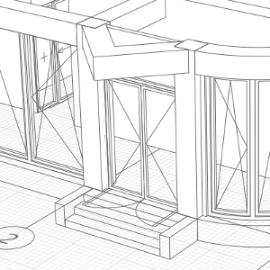
It is necessary that stair to the entrance room and an approach road to the garage be built.
Return to the 3D View tab.
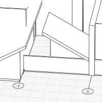
Let's build an entrance stair:
- Select the Stair tool. Select the Line by specifying two points construction mode.
- Specify the stair parameters:
- Specify the first point of the stair in the grid node opposite to the middle of the door.
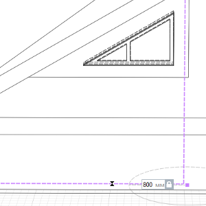
- Type the stairs length 800 mm and the angle 90° in the dynamic input fields. Left-click to fix the second point.
- Press Enter to finish the stair construction.
- To decorate the stair, build walls following the edges of the stair.
- For easy construction, use a snap to the stair base lines.
|
|
Stair position relative to baseline. |
Center |
|
|
Stair height. |
400 |
|
|
Stair width. |
2000 |

|
Number of steps. |
3 |

|
Stair shape. |
Solid |
|
|
Vertical offset. |
-400 |

|
|
Wall Height. |
400 |
|
|
Layered material. |
External wall |
|
|
Vertical offset. |
-400 |
Let's build a ramp for the driveway to the garage:
- Select the Ramp tool
 . Click the Line by specifying two points construction mode.
 - Specify the ramp parameters:
- Use a snap to the grid to construct a 2000 millimeter-long ramp opposite the gate.

|
Ramp height. |
400 |

|
Ramp width. |
3600 |
|
|
Vertical offset. |
-400 |
In the next chapter, we will build 02-Floor of the townhouse.
The 02-Floor of the townhouse will be the location of a kitchen, a sitting room, a pantry and a corridor. Also, we need to create a stair leading upwards.
Some of the objects from the 01-Floor will also be present on the 02-Floor, let's copy the 01-Floor:
- Select the Select tool.
- Click the Base level
 symbol. It will light up pink; in addition, its handle will appear.
 - Holding Ctrl, click the handle.
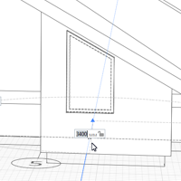
- Move the pointer slightly upwards and type 3200 mm in the dynamic input field.
- Left-click to fix the level position.
- Select the level and set the Level name to 02-Floor, set Section plane offset to 3000 mm.
Delete the objects that will not be needed in the 02-Floor:
- Press Ctrl and select:
- floor;
- gates;
- ramp and entrance stairs;
- wall between columns;
- arc wall and beam;
- Press Delete.
The next step is to construct an floor.
- Open the 2D view of the 02-Floor from the Project Explorer.
- Click the Floor tool. Click the Arc by specifying three points construction mode .
- Rebuild the floors at all levels, the layered material is Interfloor.
- Select the floor point at the intersection of grid lines B:4. Build an arc section of the floor for the balcony.
- Then switch the construction mode to Line by specifying two points .
- Construct the floor by the points. When constructing, use the snaps to the existing objects and tracking snaps. Please note that the floor offset from grid lines A and 3 is 200 mm.
- Press Enter to finish the construction.
- Build the floor opening in the same place, the Opening thickness is 200 mm.
When you get back to the 3D View tab, you will see that the bearing walls do not hide the floor:
To hide the floor with the walls:
- Select the bearing walls at the Base Level.
- Change the Height on the Parameters panel. The new height of the walls is 3200 mm.
Let's go on working with the 02-Floor only:
- Place the work plane in the 02-Floor by double clicking its symbol.
- For convenience, conceal the first level: Right-click to call the drop-down menu and select the Hide command.
The height of the load-bearing walls shall be edited:
- Right-click any of the bearing walls and select the Select > Similar on level on the shortcut menu.
- Set Height to 3200 mm.
Now let us remake the layout:
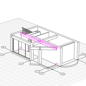
- Select the beam.
- This beam should be prolonged to the bearing wall. Click the handle under the column.
- Move the pointer to the end of the yellow base line located on grid line 3 under the beam.
- Left-click to fix the beam position.
- Build a new beam starting from the new intersection of beams to the bearing wall using snaps:
- Select the wall under the new beam and use the handle to reduce it so that the beams could rest on it:
- Then put a column under the intersection of beams.
- Select the remaining partition. Holding Alt, click the wall handle under the beam. Use snaps to move the partition to the column.
- Move the door to the partition center using handle.
- There is no Double Swing and Transom(Glass) style in the Door style list in the door parameters. Let's create it:
- Select Other style.
- Click the New door style button in the door style editor that has popped up. Set the new style name - Double Swing and Transom (Glass) - straight away.
- Create 4 panels. And set their properties so that only two doors by the center could be swung open.
- Click OK and insert a door.
- Set door parameters::
Door Height
2100
Door Width
3000
Door Style
Double Swing and Transom (Glass)
- There is no Double Swing and Transom(Glass) style in the Door style
- Use the methods that are already learnt to make up the 02-Floor interior.
Now let us go over to the external walls - let us construct the external walls following the floor contour.
- Click the Wall tool. Select the Automatically by similar construction mode.
- In the parameters, set the Wall height to 3200 mm and the Layered material to External wall.
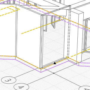
- Between the columns and at the building's corner, build the walls by similar of the floor contour. During the construction, switch the Wall position relative to baseline parameter (Right and Left) so that the yellow base lines would cross.
- The walls shall not jut out over the floor:
Let's create two new window door construction:
- On the Primary panel, click Manage styles –
 Window styles.
 - Click New window style in the window styles' editor.
- Set the new style name to Four-Unit.
- Left-click the window field. It will highlight in pink.
- Click Add vertical mullion
 .
. - In each of the two areas, repeat the operation so that there are four equal leaves.
- Then, add one more style – Three-mullion window with unequal frames.
- In the same way, create 3 mullions, then select the mullions on the edges and set the offset from the lining to 15%.
- Click OK to save the new styles.
Let's put the windows in the bays:
- Select the Window tool .
- Set window parameters:
Window Height
1500
Window Width
3200
Vertical offset
800
Window Style
Four-Unitе
- Select the insertion point in the floor corner.
- Set window parameters:
Window Height
1500
Window Width
2400
Vertical offset
800
Window Style
Three-mullion window with unequal frames
- Insert a window in a bay between the columns.
We'll finish the work with the balcony:
- The balcony door has the following parameters:
- Select the Railing tool . Click the Arc by specifying three points construction mode . Set Space between the balusters
 to200 mm.
 - Construct a balcony's railing by specifying three points.
|
|
Door height. |
2600 |
|
|
Door width. |
3600 |
|
|
Door Style. |
Four-Unit Hinged (Glass) |
Prior to finishing the work with the 02-Floor, an opening shall be made in the floor for stairs.
- Open the 02-Floor tab.
- Select the Opening tool . Select the Line by specifying two points construction mode.
- In the parameters, set Opening depth to 200 mm.
- Use snaps to construct an opening.
- Press Enter to finish the construction.
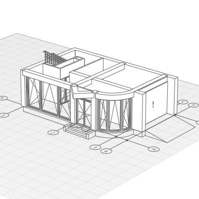
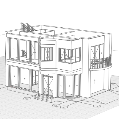
Let's look at the current model of the building:
- Go to the 3D View tab.
- Right-click the hidden levels symbols , select the Show option on the shortcut menu. For convenience, place work plane on the Base Level.
Now let us proceed to creating the next floor.
2 bedrooms and 2 bathrooms are located on the 03-Floor. Since the next floor is attic, the stairs will have to be slightly offset.
To start the construction, copy the 02-Floor. The distance between the floors is 3200 mm.
Since you have already received the knowledge sufficient to complete the floor, we suggest that you create the third floor yourself.
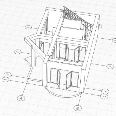
As an example, you can use the picture down below:
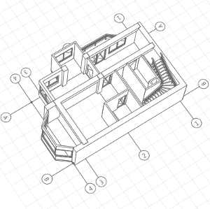
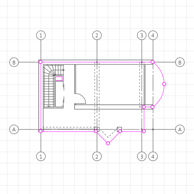
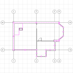
03-Floor Plan:
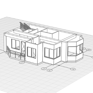
Now you can start working on the attic floor.
There will be only one bedroom on the attic floor because the bulk of the space is taken up by the roof. But we will try to bring light onto this floor.
First copy 03-Floor 3 higher by 3200 mm. Rename the level; the level name is Attic.
We'll prepare the floor for roof creation.
Delete all the external windows and doors as well as beams and columns. Open the Attic level in the Project Explorer and edit the floor by using handles.
To delete such objects, for example, beams or columns:
- Select an object.
- Right-click to open shortcut menu, click Select > Similar on level.
- Press Delete.
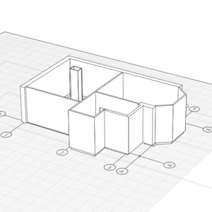
Edit the floor plan:
Attic floor in 3D view:
Let's change the height of the walls:
- Use the Select tool to select the wall on grid line 3.
- Use Select > Similar on level of the shortcut menu. Or select the walls located on grid lines A and 3 one by one, holding Ctrl.
- Change the height of the walls. The new height of the walls is 1200 mm.
- Then select the bearing wall (400 mm thick) which is parallel to grid lines A and B and set the height to 1200 mm.
- Make all the rest walls on the floor of 4000 mm height.
- Select all exterior walls and set the Vertical offset to -200 mm.
- After editing, you will get the following:
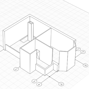
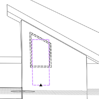
Build walls of 4000 mm height for a dormer window opposite to the exit from the stair:
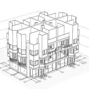
That's all, the one section of the townhouse is completed. Let's move to building all the rest sections.
The townhouse will have a single roof. It means that we are to obtain a 4-section model:
- Click the Show all option on the shortcut menu.
- On the Tools panel, click Designation – Levels . Create an auxiliary level at an arbitrary height - higher than all the existing levels.
- Arrange the working plane at a new level.
- Press Ctrl+A to select all. Then hold Ctrl and deselect the levels by left-clicks.
- Holding the right mouse button, rotate the model so that you have a top view of it.
- On the Actions panel, click the Mirror
 action.
 - Define the first point of the symmetry grid line at the intersection of grid lines B:4.
- Define the second point at the intersection of grid lines B:4:
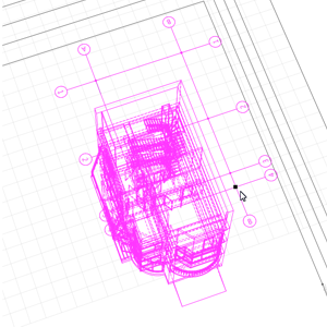
- Two townhouse sections have been constructed:
- Open the auxiliary level and edit the grid of grid lines (extend and rename the grid lines):
- Go over to the 3D View tab. Arrange the working plane at the auxiliary level.
- Select the model.
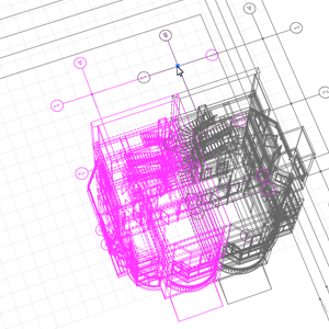
- Create a mirror. The symmetry grid line points are A:5 and E:1.
- Open the auxiliary level and edit the grid of grid lines once again. Go over to the 3D View and delete the auxiliary level.
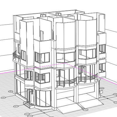
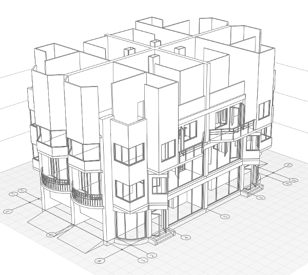
To complete the model, the only thing that needs to be created is the roof.
We will now create a complex compound roof with dormer windows on the townhouse.
Firstly, create a new material of roofing:
- On the Primary panel, click Manage styles – Materials.
- In the Materials editor, create a new material by clicking the New Material button .
- Set the new material name - Roofing.
- Choose a color for the tiles on the right side of the window:
- On the list of colors, select Other option.
- Pick an appropriate color with the palette.
- Leave the other settings unchanged. It can be assigned later.
- Click OK.
As the layered material is assigned to the roof, create it:
- On the Primary panel, click Layered materials – Manage styles.
- In the Layered materials editor, switch the Object type to Roof. Create a new material by clicking the New Material button .
- Set the new material name - Roofing.
- Set the Nonmetal material for the base layer in the right part of the window.
- Add one more layer:
- Click New layer in the right part of the window.
- Select the Roofing material and set the thickness to 10mm.
- Click New layer
- Click OK.
Hide all the levels except the Attic. Place the work plane on the Attic level.
Since the roof is of a complex shape, it would be easy to build the roof on the 2D view but edit and look at the result on the 3D view. So let's arrange the tabs for our convenience.
- Open the Attic tab.
- On the Parameters panel, set Section plane offset to 5000 mm.
- Drag the tab out of the tab bar and drop it onto one of the small squares that appear in the interface.
If you have two monitors, you may arrange the windows in different monitors.
To get acquainted with the Roof tool, let's construct a single slope roof above the bay:
- Select the Roof
 tool. Select the Line by specifying two points construction mode.
 - On the Parameters panel, set Vertical offset to 1200 mm.
- On the Edge panel, specify the following parameters:
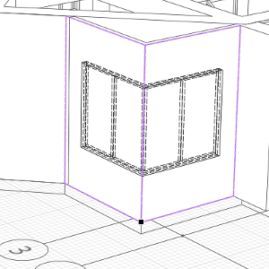
- Define the first point of the slope at the corner of the bay.
- Then use a tracking snap to define the second point.
- Next, on the Edge panel set the Edge shape
 to Gable.
 - Then specify the next point.
- Put the last point on the other corner of the bay and press Enter to complete the construction.
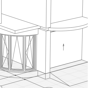
- If the slope has been built correctly, you will see on the 3D view:
|
|
Shape. |
Single Slope |

|
Slope. |
30 |

|
Slope Level. |
0 |

|
Overhang. |
500 |
|
|
Layered material. |
Roofing |
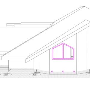
Now let us create a slope which is used to form a dormer window:
- On the Edge panel, specify the following parameters:
- Set the first edge by points 1 and 2 using the snap to partitions.
- Then, on the Edge panel, change the shape to Gable. Set point 3.
- Change the Overhang parameter to 500 mm.
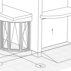
- Set point 4. Press Enter to finish the construction. Switch to 3D and make sure that the construction is correct.
|
|
Shape. |
Single Slope |
|
|
Slope. |
30 |
|
|
Slope Level. |
0 |
|
|
Overhang. |
0 |
Create a mirror copy of the created slopes for all sections by Mirror action.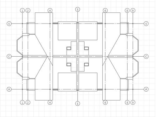
We'll construct a hipped roof over the whole building:
- On the Edge panel, specify the following parameters:
- Build the roof by four points without changing parameters of the edges. Press Enter to finish the construction.
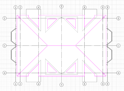
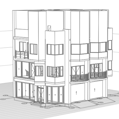
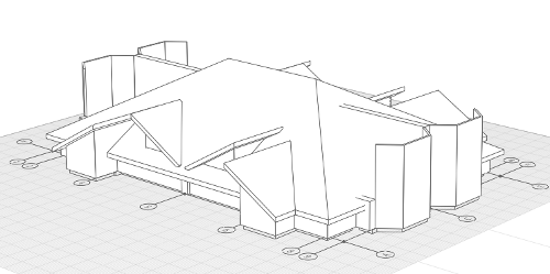
- The created model in the 3D view:
|
|
Edge shape. |
Single Slope |
|
|
Slope. |
30 |
|
|
Slope Level. |
0 |
|
|
Overhang. |
500 |
Let us finish up the roof construction:
- In the Edge parameters, set the Edge shape to Slope.
- Use snaps to define the first point of the slope.
- Then the second point of the slope.
- Then, in the Edge parameters, change the shape to Gable.
- Select a point on the ridge of the hipped roof.
- Set the next point symmetrically to point 2 in relation to B grid line.
- Then change the shape over to Slope again.
- Set the last point symmetrically to point 1.
- Change the shape over to Gable for the last time. Then press Enter to finish the construction.
- Select a new double-pitch roof.
- Make a Mirror of the double-pitch roof in relation to grid line 5.
Now all that is left is to create windows:
- Go to the 3D tab.
- Select the Window tool .
- Set window parameters:
- Insert a Window:
- Set window parameters:
- Insert a window in a bay using the snap to the internal door:
- In the Parameters panel, specify:
- Insert a Window:
- Select all the three windows and use the Mirror action to arrange the windows in all the sections.

|
Window aperture shape. |
Left semi-trapezoidal aperture. |
|
|
Window Height. |
700 |
|
|
Window Width. |
1200 |

|
Window Trapezium Height. |
700 |
|
|
Vertical offset. |
1800 |
|
|
Window style. |
Double |
|
|
Window Height. |
1400 |
|
|
Window Width. |
800 |
|
|
Window Trapezium Height. |
450 |
|
|
Vertical offset. |
500 |
|
|
Window style. |
Single |
|
|
Window aperture shape. |
Trapezoidal aperture. |
|
|
Window Height. |
1200 |
|
|
Window Width. |
1600 |
|
|
Window Trapezium Height. |
400 |
|
|
Vertical offset. |
900 |
|
|
Window style. |
Double |
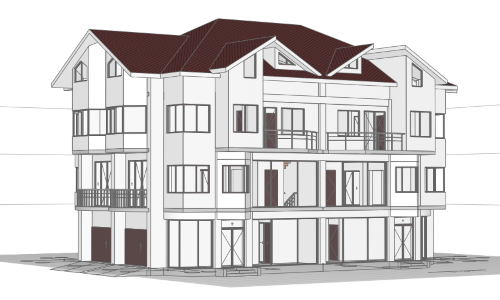
The roof is done: