Route Editing
An automatically generated route can be edited using 3D vertices. Route points can be added to or changed from vertices to modify the route. At the same time, the objects placed on the route are also changed, for example, the length of pipes. To edit the route, hide the objects placed on it or select the visual style Wireframe for them.
In 3D View, you can edit route parameters

|
System style. Defines the designation and color of the system. |

|
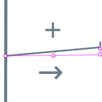
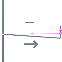
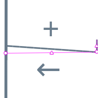
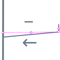
Slope. The slope is set for the entire section of the route and defines the location of pipes and ducts on the horizontal segments of the route. The slope direction depends on the route construction direction. The slope value is calculated from the beginning of the route and can be positive or negative.
|
After editing is complete, place the parts manually or automatically on the route.

|
The maximum slope is 87.4 %, to set a higher slope edit the route with the handles. |
Route Editing by Vertices
- Select a segment of route on the 3D view or level plan with the Select tool.
- Left-click a vertex
 on a route or hold the pointer onto the vertex and select the Move option on the shortcut menu appeared.
 - Specify the new point position
Moving Route Segment
- Select a segment of route on the 3D view or level plan with the Select tool.
- Left-click a midpoint
 on a route or hold the pointer onto the vertex and select the Move option on the shortcut menu appeared.
 - Move the pointer and then fix the vertex position with the left mouse click.
|
|
In order for vertices and route segments to be moved, they must have degrees of freedom for movement. Degrees of freedom are limited by branches and objects that form the route. Add vertices to the route to increase the number of degrees of freedom. |
Removing and Adding Vertices on Route
- Select a segment of route on the 3D view or level plan with the Select tool.
- Move the pointer to the segment midpoint .
- Select the Add vertex option.
- Left-click to fix the new vertex position.
- Select a segment of route on the 3D view or level plan with the Select tool.
- Move the pointer to the vertex .
- Select the Remove vertex option.
To add a vertex:
To remove a vertex:
|
|
If a vertex forms a segment that is joined by a branch, the vertex cannot be deleted. |
Removing Vertices by Combining
- Select a segment of route on the 3D view or level plan with the Select tool.
- Click the vertex on a route with the left mouse click.
- Combine the vertex with the nearest vertex on the route.
Adding a route point
You can split a route into two by adding a route point from the midpoint menu.
To add a route point to an existing route:
- Select a route using the Select tool.
- Move the pointer to the segment midpoint .
- Select Add route point.
- Specify the location of the new route point on the selected route. The route is split into 2 routes that connect at the route point.
Replacing a route point with a vertex
If a route point is connected to two routes of the same engineering system and the directions of the routes coincide, it can be replaced by a vertex.
To replace a route point with a vertex:
- Select the route point connecting the two routes.
- Move the pointer to the insertion point.
- Select the Replace with vertex option.
In addition, you can replace the route point with a vertex in the system tab:
- In the System tab, select the route point that connects the two routes.
- Select the Replace with vertex
 command.