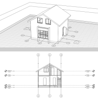
Section
The Section  designation is intended to create designations of sections and obtain views of buildings with the sections of the following types:

|
Section in one plane. To form it, one cutting plane is used. |

|
Section in parallel planes. To form it, two or more parallel planes are used. |

|
Section in two intersecting planes. To form it, two intersecting planes are used. |
Section Parameters:

|
Section name. |

|
Section line extension. It defines the distance from the extreme handle to the section name. |

|
View depth plane offset. Defines the distance from the cutting plane to the view depth plane. The view will not display objects that are completely outside the view depth plane. |

|
Object part beyond view depth plane. It determines whether to show or hide parts of objects that are partially outside the view depth plane. |

|
|

|
The parameters may be modified during the construction process and when editing. Press Enter to fix the parameter values.
The handles of the section and the View depth plane offset  determine visibility area where objects are displayed in the section view.
Section symbol is linked to the working plane; if a working plane is moved to another level, the section symbol remains on the working plane. This allows to open a section for viewing from any position on the work plane.

All the snaps and accurate construction are available for section construction.
In order to modify, copy or relocate a created section, select it by using the Select  tool. When you select a section in the model, the boundaries of the section visibility area are displayed.

|
View direction is determined when constructing the section symbol. To change view orientation use the Flip command in the context menu. |

|
If section plane coincides with the object face, this face will be displayed on the cut in any direction of view. |
In order to view a section image, do the following:
- On the work plane, right-click the Section image with the Select
 tool.
tool. - Select Open in the context menu.
or
- Click Open Project Explorer
 .
. - Left-click the section thumbnail.