Elevation Mark
In order to specify the elevation marks on the view section and elevations, do following:
- When formatting a drawing, select the Dimension
 tool.
- Select the Elevation mark
 dimension type.
- On the elevation or section view, specify the zero height point
- Then select the point for which it is required to set an elevation mark.
- Move the mouse cursor so that the mark is in the required position.
- Fix the elevation mark position by left-clicking the mouse.
- To continue constructing, select next point, the elevation mark of which you want to define.
- Press Esc to finish the construction.
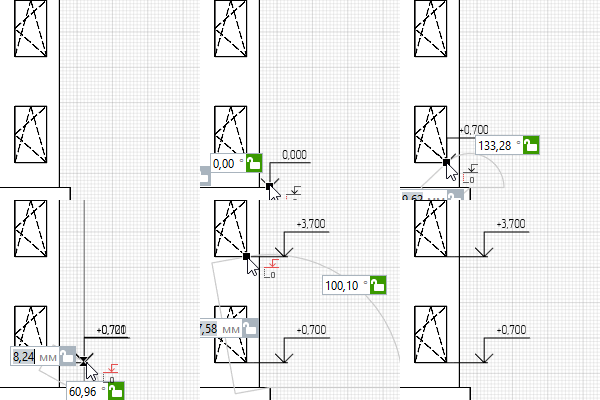
If elevation marks are plotted in the view of a section or elevation, the elevation marks are automatically updated when the model is changed, but only if they were built using object snaps: the object end point  .

|
In order to specify the elevation mark on the drawing plan, use the Callout or Tag. |